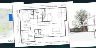
A complete set of construction drawings decides whether your project clears plan review, whether your subs price it accurately, and whether your client understands what they signed.
Most delay, dispute, and “that’s not what I approved” conversations trace back to a drawing that was missing, unclear, or never shared.
Get it right and the job runs quietly.
Get it wrong and you’ll pay three times over: in change orders, in rework, and in the relationship with a client who feels misled.
This guide covers every type of drawing a residential builder deals with, what each one is for, the symbols you’ll read on them, and how to pull a complete set together.
Key Takeaways
- Construction drawings serve three audiences at once: the plan reviewer, your subcontractors, and the client who has to approve the design.
- A set of drawings for a residential project is often assembled from several sources, with architectural sheets from the builder or designer and structural, electrical, plumbing and mechanical sheets from trade partners and engineers.
- Reading drawings comes down to a small vocabulary of line types, floor plan symbols, view markers and dimension conventions that repeat on every project.
- Cedreo lets contractors and builders produce the architectural layer (site plans, 2D and 3D floor plans, electrical plans, elevations, sections and renderings) from one project file, then export to CAD formats when a trade partner needs to take it further.
“Why trust us? Here at Cedreo, we’ve got 20+ years of experience working with housing pros in the home design space. So we know what it takes for contractors and builders to create residential project designs that help them land more clients!”
See How You Can Create Complete Projects with Cedreo
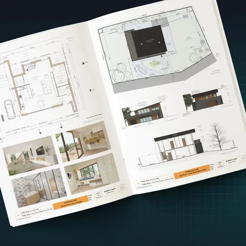
Plans – Get site plans, 2D floor plans, electrical plans, cross sections and elevation views — with all the technical details you need for a comprehensive project overview.
3D Visualizations – Use interior and exterior 3D renderings as well as 3D floor plans to help clients understand the finished project.
Documentation – Manage all your visual documents in one place, so it’s easier to present and sell your projects.
No credit card required, no commitment
What Are Construction Drawings and Who Reads Them?
Construction drawings are the scaled technical drawings that show how a building gets built: layout, exact dimensions, materials, and systems.
They’re the reference every party works from, and they replace verbal description with something measurable.
Versions of these drawings serve three very different audiences at once.
- Your client reads them (or honestly, reads the pictures in them) to understand and approve what they’re paying for.
- The plan reviewer reads them to confirm the design meets local building codes and zoning limits before a permit is issued.
- Your subcontractors read them as build instructions, and they price from them at bid time.
A complete package has the drawings that satisfy all three.
What Does a Set of Residential Construction Drawings Include?
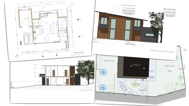
A residential drawing set typically runs somewhere between eight and twenty sheets, depending on complexity and how much your jurisdiction asks for.
A straightforward single-family home sits at the low end, while a custom build with complex rooflines and a finished basement may even be beyond that range.
Here’s what a typical set covers:
- Cover sheet and general notes: Project information, the drawing index, applicable codes, and the abbreviations legend.
- Site plan: Where the structure sits on the lot, with setbacks, property lines, and access.
- Floor plans: The room-by-room layout of each level, with actual dimensions and wall thicknesses.
- Elevations: What the building looks like from each side, with heights and exterior finishes.
- Sections: Vertical cuts showing how floors, walls, and the roof structure relate.
- Schedules: Tabulated lists of windows, doors, and finishes, keyed to tags on the plans.
- Details: Close-up drawings of connections the main sheets can’t show at scale.
- Specifications: Written material specifications and technical specifications covering products, grades, and standards.
Scales matter throughout, since a plan at 1/4″ = 1′ and a detail at 1 1/2″ = 1′ carry very different levels of information.
PRO TIP! Build your drawing index before you build the drawings. Listing every sheet you’ll need at the start makes the gaps obvious while they’re still cheap to fill, instead of two days before submission.
Construction Drawing Symbols: How to Read a Construction Drawing
Reading a construction drawing comes down to four things: line types, plan symbols, view markers, and dimension conventions.
Learn those and almost any residential sheet becomes readable, no matter who drew it.
Line Types and What They Mean
Line weight and line style carry meaning, and they’re the most fundamental symbol system on any drawing.
- Solid lines: Visible elements cut by or seen in the current view, drawn heavier as they approach the cut plane.
- Dashed lines: Hidden elements, or things above the cut plane like an upper cabinet, a beam, or a roof overhang.
- Centerlines: Long-short-long lines marking axes of symmetry, column grids, and fixture centers.
- Dimension lines: Thin lines with terminators at each end, carrying the measurement between two points.
For example, on a floor plan, imagine the building is sliced horizontally about 4 feet above the floor and you’re looking down:
- Walls that the imaginary cut passes through are usually drawn with heavy/thick lines.
- Things you can see below the cut plane, like cabinets or fixtures, may be drawn with lighter/thinner lines.
- Objects above or hidden from view may use dashed lines.
Common Floor Plan Symbols
Floor plan symbols are standardized shorthand for physical elements in a plan view, and the same handful shows up on every residential project.
- Doors: A rectangle in the wall with an arc showing swing direction.
- Windows: Three thin parallel lines drawn within the wall thickness.
- Stairs: Parallel lines with an arrow marking direction of travel, labeled UP or DN.
- Walls: Solid fill or hatching, with the pattern often indicating material.
- Electrical fixtures: Small circles, arcs and letter codes for outlets, switches, and ceiling lights.
There are hundreds more, and our A-Z guide to floor plan symbols covers the ones worth memorizing, with a separate breakdown of electrical symbols if that’s where you get stuck.
Elevation and Section Symbols
View markers tell you where you’re standing when you look at a drawing, and they’re the symbols most likely to confuse a builder or client reading sheets prepared by an architect.
- Section cut indicators: A line across the plan with arrows showing the cut and view direction, plus a bubble keying it to the sheet where that section drawing lives.
- Elevation markers: A circle with a triangle pointing toward the face being drawn, numbered to match the elevation sheet.
- Level and datum markers: Small flags noting finished floor heights against a fixed reference point.
Our guide to elevation view vs. plan view covers how a vertical perspective differs from the view looking down.
Dimension and Annotation Conventions
Dimensions on residential drawings are usually arranged in dimension strings, and reading them correctly means understanding both the measurement and what the measurement is referencing.
- Overall dimensions show the full width or length of a building or major section.
- String dimensions break that overall measurement into smaller segments for walls, openings, and other elements.
The important part is knowing where each dimension is measured to.
Depending on the drawing set, dimensions may reference the face of framing, finished face of a wall, centerline of a wall, or centerline of an opening.
Room dimensions can also be shown in different ways.
A listed room size may represent the clear finished space, framing dimensions, or another reference established by the designer.
Callouts and reference bubbles point you to another drawing where an area is shown in greater detail.
They typically identify both the detail or view number and the sheet where it can be found.
Callouts and annotations can also just provide a note with additional details regarding part of the design.
Cedreo advantage: Cedreo uses standard residential drawing symbols and generates dimension lines automatically while still giving you the power to add custom dimensions and annotations. See floor plans with dimensions for what that looks like on a finished sheet.
Types of Construction Drawings
Construction projects need drawings from several disciplines, and the types of construction drawings below are the key elements a residential builder has to pull together.
Site Plans and Plot Plans
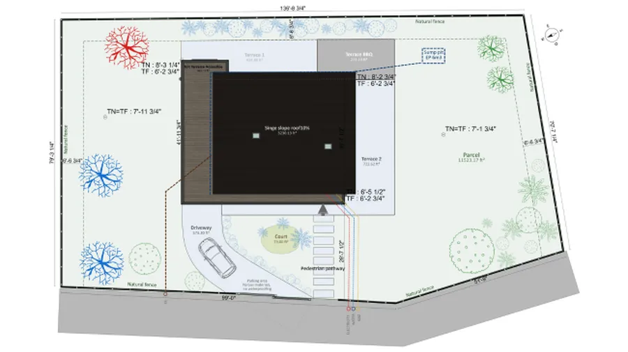
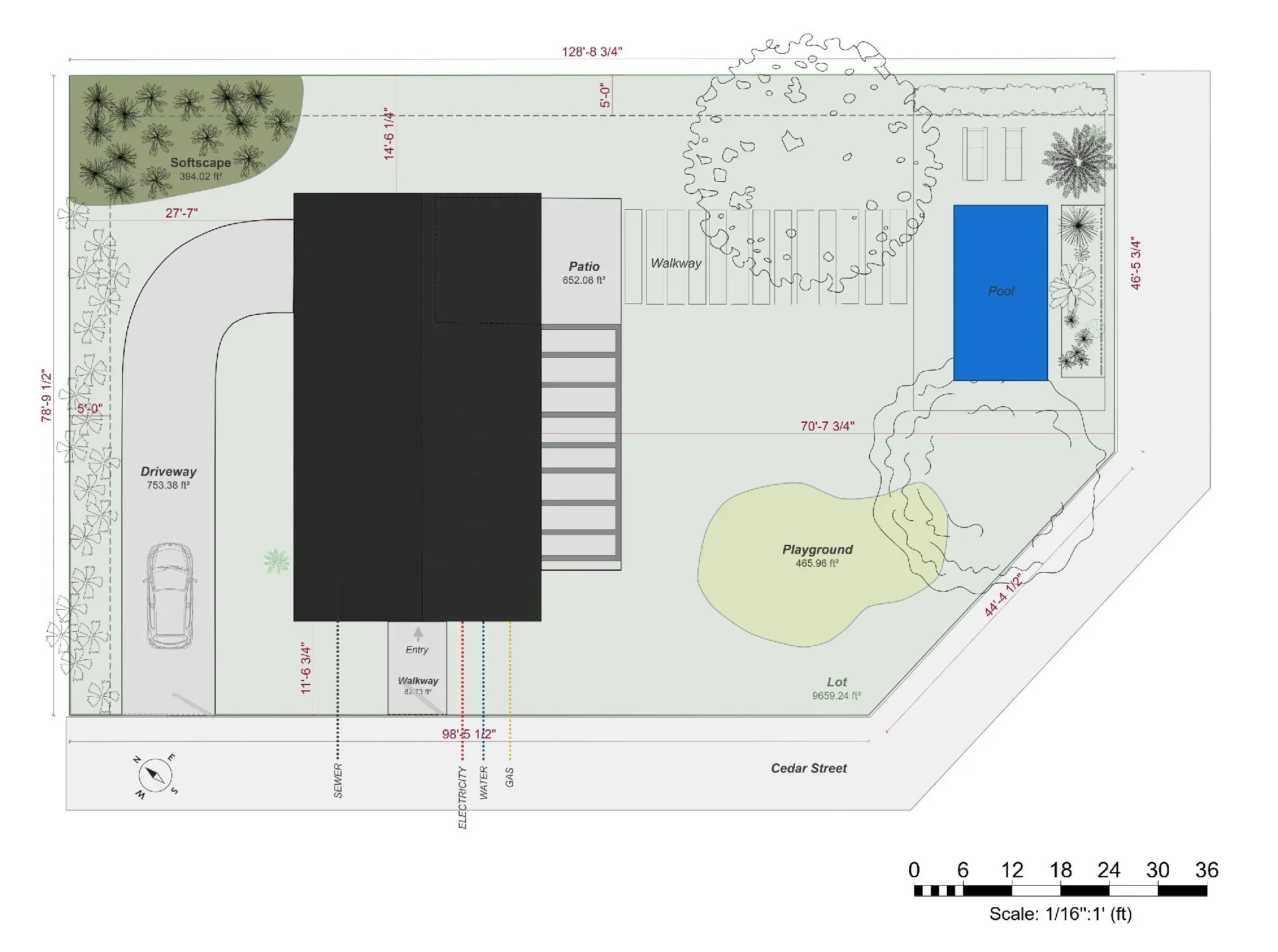
Site plans show the structure’s relationship to the lot and to surrounding structures: footprint, setbacks, driveways, utilities, grading and drainage.
They set the constraints every other drawing works inside, which is why site plan drawings are usually one of the first to produce.
Plot plans cover the legal side: surveyed boundaries, easements, right-of-way and existing conditions.
In practice the line between them is blurry, and across the USA many jurisdictions use the two terms interchangeably or want both on a single sheet.
Some building departments ask for the surveyed boundaries and the proposed layout as two separate documents, others treat one drawing as both, so check what your local AHJ calls it before you draw anything.
Who produces it: The builder or designer typically prepares the site plan using property information from sources such as a licensed surveyor, recorded plat, deed, or municipal/county property records.
When precise or legally verified property boundaries are required, those boundaries should come from a licensed surveyor.
Cedreo advantage: Site plans produced in Cedreo’s site plan software show the building’s position on the lot, setbacks and site features in both 2D and 3D, so a client can see the entire project site the way it’ll actually sit.
Our guide on what a site plan includes covers the components in detail.
Floor Plans
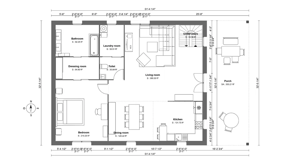
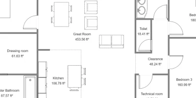
Floor plan drawings are top-down views of each level showing room layout, wall positions, openings, and exact dimensions.
The 2D version is the reference trades work from, while 3D plans do the selling, and a complete residential package benefits from both.
Who produces it: The builder, designer, or architect.
Cedreo advantage: Cedreo produces both 2D and 3D plans from the same project file, so a change to the 2D drawing updates the 3D view as you work, with no redrawing.
When a trade partner needs CAD files, just export to DXF.
Elevation Drawings
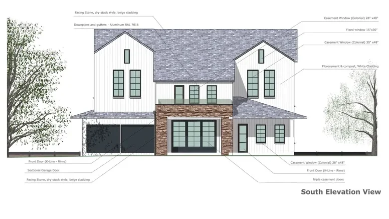
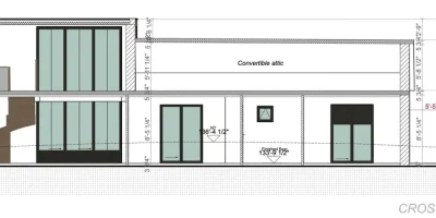
Elevation drawings are flat views of the building from outside, showing exterior finishes, window and door placement, roof pitch, and heights.
Residential work typically needs four (front, rear, left side, right side), and they’re what a plan reviewer checks height limits against and what a client uses to picture the house from the street.
Who produces it: The builder, designer, or architect, generated from the floor plan and roof design.
Our step-by-step guide to drawing an elevation walks you through the process.
Section Drawings
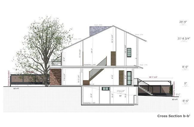
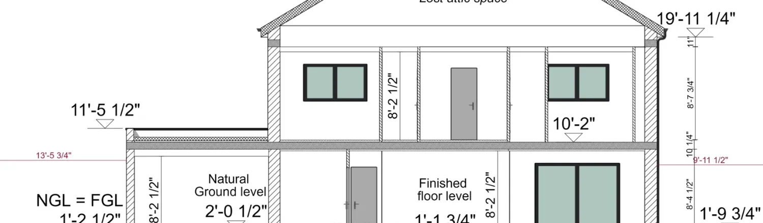
Section drawings are vertical cuts through the building that reveal what a plan view can’t: wall assemblies, ceiling heights, floor-to-floor relationships, and roof structure.
They’re most often needed for complex roof lines, split-level transitions, and anywhere the relationship between structural elements isn’t obvious from above.
On remodels they’re worth drawing wherever new work meets existing structural elements at an awkward height.
Who produces it: The builder, designer, or architect, cut from the same model as the plans and elevations.
Cedreo advantage: Cedreo produces section and elevation drawings from the 3D model so there’s no need to manually draw them.
Landscape Drawings
Landscape drawings detail the outdoor environment around structures: planting, hardscape, outdoor lighting, and irrigation.
The distinction from a site plan is worth being precise about, because the two get confused constantly:
- A site plan shows structures and boundaries
- Landscape drawings focus on the space between them.
Who produces it: A landscape designer or contractor, sometimes the builder on smaller jobs.
Excavation Drawings
Excavation drawings show cut and fill, foundation depths, grading, and drainage systems across the entire construction site.
They’re derived from the site plan and foundation design rather than drawn independently.
They cover the whole project site including access and spoil storage, and no design software produces them automatically.
They’re also the first drawings anyone opens on a live construction site, because nothing else gets built until the excavation is right.
Who produces it: The contractor or a civil engineer.
Structural Drawings
Structural drawings show the foundation plan, framing layout, beam and header sizes, and the connection details that carry the building’s loads.
In the US, not every residential permit needs stamped structural drawings.
Most residential codes include a prescriptive path, so if you follow the span tables in the International Residential Code with conventional wood framing, the tables do the engineering for you.
Once a project leaves that path, engineering is required to demonstrate structural integrity, and projects leave it more often than builders expect:
- Non-standard spans or unusually long clear openings.
- Complex or irregular roof geometry.
- Removing or modifying load-bearing walls, especially in remodels.
- Additions tying into existing framing of unknown capacity.
- High wind, high snow, or high seismic zones.
Requirements vary a lot by jurisdiction, so confirm with your building department before assuming either way.
Who produces it: A licensed structural engineer, or in some jurisdictions a certified designer working within the prescriptive path.
Sizing structural components sits well outside what home design software like Cedreo does. However you can export the core floor plans in CAD formats to hand off to an engineer.
Electrical Drawings
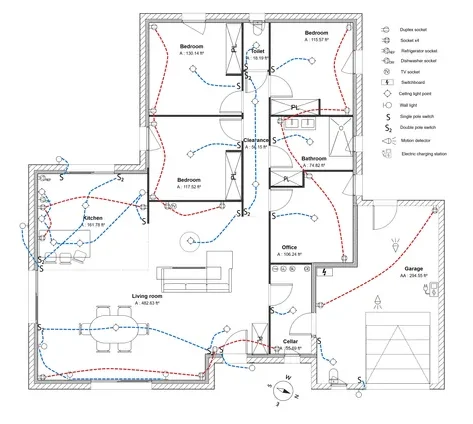
Electrical drawings show panel location, circuit routing, outlet and switch placement, and light fixtures throughout the home.
On residential work they range from a simple symbol layout on a floor plan to full wiring diagrams with load calculations and system specifications for larger electrical systems.
The basic version is within a builder’s reach.
in Cedreo you place electrical symbols from the Technical catalog onto a copy of your plan and draw the circuit runs, and our guide on how to create an electrical plan covers the workflow.
For anything more involved, including load calculations and panel schedules, you’ll want a licensed electrician or dedicated electrical/CAD software.
Who produces it: The builder or designer for basic layouts, the electrical contractor for anything engineered.
Plumbing Drawings
Plumbing drawings show supply and drain routing, fixture locations, water heater placement, shutoff valve locations, and other information needed to install the plumbing system.
Depending on the jurisdiction and complexity of the project, the permit set may include detailed plumbing plans or only enough information for the plumber and plan reviewer to understand the proposed system.
Plumbing documentation may also include a plumbing isometric drawing.
An isometric shows the piping system in a simplified three-dimensional view, making it easier to understand how drain, waste, and vent lines connect vertically and horizontally throughout the building.
These drawings are especially useful for showing fixture connections, pipe sizes, vents, cleanouts, and changes in elevation that may be difficult to understand from a floor plan alone.
Who produces it: Plumbing drawings are typically prepared by the plumbing contractor, licensed plumber, designer, or engineer, depending on the project and local requirements.
While Cedreo can produce drawings showing the location of plumbing finishes, detailed plumbing drawings are outside what home design software like Cedreo does. However, you can export the relevant floor plans in CAD formats and provide them to a plumber or engineer as a base for developing the plumbing plans and isometric drawings.
Mechanical and HVAC Drawings
Mechanical drawings focus on duct routing, equipment locations, ventilation paths, and the load calculations used to size the system.
They help show how conditioned air will move through the house and how ductwork, equipment, and penetrations need to coordinate with the framing, plumbing, and electrical systems.
Depending on the project, the documentation may include furnace or air-handler locations, outdoor condenser locations, supply registers, return-air grilles, exhaust fans, fresh-air intakes, duct sizes, and equipment schedules.
On simpler residential projects, the HVAC contractor may handle much of this layout and sizing directly rather than issuing a detailed mechanical drawing set.
Who produces it: The HVAC contractor, mechanical designer, or mechanical engineer, depending on the project and local requirements. Detailed HVAC design generally sits outside Cedreo’s scope.
Roof Plans
Roof plans are top-down views showing the shape and layout of the roof, including slopes, ridges, hips, valleys, overhangs, and drainage direction.
Depending on the project, they may also show roof penetrations, chimneys, vents, skylights, gutters, downspouts, and notes identifying roofing materials or assemblies.
Roof plans help the builder understand how the roof geometry comes together and coordinate framing, drainage, exterior elevations, and material quantities.
Who produces it: The builder, designer, or architect.
Our roof plan fundamentals guide covers what to show and how to save time on them.
Detail Drawings: How Building Components Connect
Detail drawings focus on a specific connection, assembly, or small area so it can be understood more clearly than on the main drawings.
They show how different building components come together at locations where construction can become complicated or where mistakes are costly.
Common examples include foundation-to-wall connections, window and door flashing, stair construction, roof-to-wall transitions, waterproofing details, and structural connections.
Details are usually drawn at a larger scale than plans, elevations, or sections and are referenced using callouts that tell the reader where to find the corresponding detail.
Who produces it: The architect, designer, or engineer responsible for the assembly.
As Built Drawings
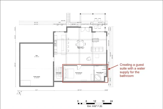
As-built drawings document significant changes made during construction so the final record reflects the building more closely than the original construction drawings.
If walls move, pipe routes change, equipment is relocated, or other field conditions require changes, those revisions can be marked on the drawings during construction and compiled into an updated record at project closeout.
As-built drawings can be especially useful for future renovations, repairs, and maintenance because they provide a record of changes that may no longer be visible once walls and ceilings are closed.
However, you shouldn’t assume as-built drawings are a precise survey of every concealed condition unless they were specifically measured and verified for that purpose.
Who produces it: Typically the contractor, based on field markups and project records, although architects, engineers, or surveyors may prepare or certify portions of the final record depending on the project.
Our full guide on as-built drawings covers how to keep them current without it becoming a second job.
Other Plan Types: Fire Protection, Ceilings, Finishes, Schedules and Perspectives
Five more drawing types that may show up depending on the project.
| Drawing type | What it shows | Who produces it |
| Fire protection drawings | Smoke and carbon monoxide alarm locations, and where sprinklers are required, the suppression system and its piping | Fire protection contractor or engineer for sprinklers, builder or electrician for alarms |
| Reflected ceiling plans | A ceiling-side view: ceiling heights, light fixtures, fans, HVAC registers, coffered or tray detailing | Designer, electrician, or HVAC contractor |
| Finishing drawings | Surfaces and interior details the client sees: flooring, wall finishes, trim, cabinetry, tile layouts | Builder, designer, or interior specifier |
| Schedules | Windows, doors, finishes and hardware with sizes and material specifications, keyed to plan tags | Whoever produced the sheets they key to |
| Perspective drawings | The project as the eye sees it, with depth and vanishing points instead of a flat view | Builder or designer, from the 3D model |
Cedreo advantage: A rendering doesn’t replace a finish schedule, and it shouldn’t try: the schedule is what the tile guy orders from. But no homeowner can picture a room from a written spec, which is where 3D renderings come in. Cedreo generates them from the same project file as your plans in about five minutes each.
House Construction Drawings: What a Complete Residential Set Looks Like
A complete house construction drawing set organizes the information needed to permit and build the home into clearly identified sheets, usually grouped by discipline.
Many drawing sets use discipline letters such as A for architectural, S for structural, E for electrical, P for plumbing, and M for mechanical.
Larger and more formal sets may follow conventions from the United States National CAD Standard, although residential drawing organization varies considerably by designer, builder, and jurisdiction.
Sheet numbers also help identify where information belongs.
A drawing might be labeled A-101 for an architectural floor plan or A-201 for an architectural elevation.
The exact numbering system can vary, so always use the drawing index on the cover sheet to understand how a particular set is organized.
| Series | What’s on those sheets | Who usually produces them |
| G | General: cover sheet, drawing index, code data, abbreviations | Builder, designer, or architect |
| A | Architectural: site plan, floor plans, elevations, sections, details | Builder, designer, or architect |
| S | Structural: foundation plans, framing plans, structural sections and connection details | Structural engineer or other qualified design professional |
| E | Electrical: service/panel information, circuits, receptacles, switches, lighting and fixtures | Electrical designer, electrician, builder, or engineer |
| P | Plumbing: water supply, drain-waste-vent systems, fixture locations and plumbing details | Plumbing contractor, designer, or engineer |
| M | Mechanical/HVAC: equipment, ductwork, supply and return locations, ventilation and related information | HVAC contractor, mechanical designer, or engineer |
Not every residential project needs a separate sheet series for every discipline.
On a straightforward house, some electrical, plumbing, or HVAC information may be incorporated into the architectural set or developed separately by the trade contractor.
More complex projects and jurisdictions with more detailed plan-review requirements may require dedicated drawings from engineers or licensed trades.
For the builder or residential contractor, the job is often as much about coordination as drawing.
Architectural plans establish the overall design, while structural, electrical, plumbing, and mechanical information must agree with them.
A few habits make that coordination easier:
- Establish the architectural layout before the trades begin detailed design
- Clearly identify revisions
- Make sure everyone is working from the current drawing set (When one trade works from an outdated plan, conflicts quickly appear in the field)
Cedreo advantage: Cedreo produces the architectural sheets of a residential package (site plan, 2D and 3D floor plans, exterior elevations, sections, a basic electrical plan, and 3D renderings) from a single project file. That’s the design and client approval layer of the drawing sets you own. Then structural, plumbing and mechanical sheets are compiled separately from trade partners and engineers.
How to Create Construction Drawings for a Residential Project
Start by choosing the right drawing workflow, then develop the project in a logical sequence so the plans, elevations, sections, and details stay coordinated.
Start by Choosing Your Drawing Method: Hand Drafting, CAD, or 3D Design Software
There are three ways to produce residential building drawings, and most builders end up combining them rather than picking one.
| Method | Best for | The trade-off |
| Hand drafting | Early sketches, simple concepts, field markups, and quick problem-solving | Difficult to revise, share, coordinate, and reproduce accurately |
| Computer aided design (CAD) | Precise technical drawings, detailed documentation, structural coordination, and files shared with engineers or trades | Requires more drafting skill and can be slower for early design exploration |
| 3D design software | Concept development, client presentations, coordinated architectural drawings, visualization, and rapid design changes | Capabilities vary by platform, and specialized structural or MEP documentation may still require CAD, engineering software, or trade-specific tools |
For many residential projects, a hybrid workflow works best.
You can design the project in 3D, while CAD files are exported when an engineer, architect, or trade contractor needs to develop more specialized technical drawings.
That is why features such as DXF export matter.
They allow architectural drawings to serve as a starting point for structural, mechanical, electrical, or plumbing work without requiring another professional to recreate the entire plan from scratch.
If you’re comparing specific digital tools, our guide to blueprint software for residential pros breaks down the main options.
Start with the Site Plan and Lot Constraints
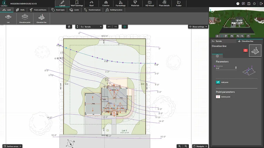
The site plan comes first because it sets the constraints everything else is designed within: setbacks, easements, lot coverage limits, and utility locations.
Before finalizing the floor plan, identify the property boundaries, required setbacks, easements, access points, utility locations, topography, and any other site conditions that could affect the building footprint.
Property information may come from a survey, recorded plat, deed, municipal or county records, or other available site documentation.
Confirm applicable setbacks and zoning requirements with the local authority having jurisdiction before the design is finalized.
This early site work helps prevent a common problem: developing a house plan only to discover that the footprint, driveway, utilities, or other features conflict with the lot.
Develop the Floor Plan
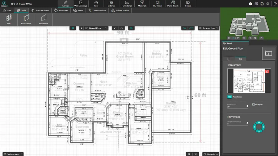
The floor plan becomes the primary reference for the architectural design, establishing room relationships, wall locations, openings, circulation, and overall dimensions.
A typical workflow is:
- Block out the overall footprint, room relationships, and circulation.
- Establish key dimensions based on how the spaces will actually be used.
- Set exterior and interior wall assemblies and thicknesses.
- Place doors and windows, checking clearances, furniture layouts, and egress requirements where applicable.
- Add dimensions, room names, annotations, and other information needed to communicate the design.
The process is iterative.
Changes to elevations, roof geometry, structure, or building systems may require adjustments to the floor plan as the design develops.
Our step-by-step guide to drawing floor plans covers each stage in more detail.
Cedreo advantage: Cedreo’s floor plan software starts with the 2D drawing and builds the 3D model as you draw, so elevations, sections and renderings all come off the same geometry. Change the plan and the connected views follow, instead of being redrawn one at a time.
Generate Elevations and Sections from the Floor Plan
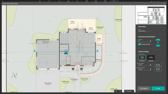
Once the basic floor plan is established, elevations and sections help test and communicate the building vertically.
Develop these drawings alongside the floor plan rather than only after it is finished.
An elevation may reveal an awkward window alignment, while a section may uncover a roof, stair, or ceiling-height conflict that requires the plan to change.
For many residential projects, the permit or construction set includes exterior elevations and one or more building sections, depending on the complexity of the home and local requirements.
When the drawings are generated from the same model, changes can remain coordinated across plans, elevations, sections, and 3D views.
CAD exports can also give engineers or trade partners a base for developing more specialized drawings.
Build the Client Presentation and Get Design Approval
Lock the client’s approval on the core design before a single trade partner starts drawing, because everything that comes next gets built on this layout.
Send an unapproved floor plan out for electrical, plumbing and HVAC drawings and one client conversation about moving the kitchen means paying three trades to redraw work you already paid for.
So get the design signed off first and those drawings only get produced once.
What works is a short presentation document that puts the plans next to the visuals, so the technical drawings and the picture of the finished house tell the same story on the same page.
Cedreo’s Folder step is built for exactly this, and the workflow is short:
- Go to the Folder step and create a new document.
- Set the document name, then choose the layout (orientation and format) and your margins.
- Drop in the project elements you want the client to see: 2D and 3D floor plans, the site plan, elevations, and your interior and exterior renderings.
- Add surface area tables so the client can see room-by-room square footage next to the layout.
- Add your company logo so what lands in their inbox looks like it came from your business.
- Click Download, choose Digital for something you’re emailing or Print for a hard copy, and generate the PDF.
Walk them through it in person or on a call rather than emailing it cold, and note every change they ask for before you touch the drawings.
The builders we work with who present this way tend to come out of the meeting with a decision instead of a maybe.
Our guide to floor plan presentations covers how to run that conversation.
Coordinate Structural, Plumbing, and Mechanical Drawings
Your job is not only to produce the architectural drawings, but also to make sure the structural, plumbing, mechanical, and other disciplines are coordinated with them.
Bring structural engineers, architects, and key trade partners into the process early enough that their requirements can influence the design.
Structural framing, beam locations, plumbing stacks, duct routes, equipment clearances, and other systems can all require changes to the architectural layout.
Provide consultants and trade partners with the current architectural drawings and, when appropriate, CAD files such as DXF so they can develop their work from the same underlying geometry.
Each discipline is responsible for the technical design of its own system, but the builder or project lead is responsible for making sure those systems work together as a coordinated whole.
So be sure to review the drawings for conflicts such as:
- Beams interfering with ceiling heights or duct runs
- Plumbing stacks conflicting with framing
- Mechanical equipment lacking adequate clearance
- Ductwork crossing structural members
- Panel or equipment locations conflicting with walls, doors, or cabinetry
- Openings that do not align between architectural and structural plans
The goal is to resolve these conflicts before construction begins, when changes are much easier and less expensive to make.
Revisions are inevitable, so maintain clear revision dates and make sure everyone is working from the current set.
Assemble the Package for Permit Submission
Assembly means putting every discipline’s sheets into one indexed, consistently numbered set a plan reviewer can move through without hunting.
Work through a short checklist before you submit:
- Confirm the sheet index matches the sheets actually in the set.
- Check that every reference bubble points to a sheet that exists.
- Verify scales are stated on every drawing and consistent within each series.
- Reconcile dimensions where the architectural and structural sheets overlap.
- Confirm the cover sheet lists the applicable building codes for your jurisdiction.
Requirements vary significantly between jurisdictions, so verify the checklist with your local building department rather than assuming last project’s list still applies.
Share the Drawing Package with Subs for Bidding
The more complete and coordinated the bid documents are, the more accurately subcontractors can price their work.
Missing information often turns into assumptions, exclusions, allowances, or change orders later.
So give each bidder the current drawings, specifications, schedules, and other documents that could affect their scope.
For coordination, it is also helpful to provide access to the complete drawing set so subcontractors can see how their work interacts with other trades.
Different trades will focus on different parts of the set:
- Framing contractors: Floor plans, roof plans, elevations, sections, structural plans, and framing details.
- Electrical contractors: Floor plans, electrical drawings, lighting layouts, reflected ceiling plans where applicable, equipment information, and relevant schedules.
- Plumbing contractors: Floor plans, plumbing plans or fixture layouts, sections, equipment locations, and applicable schedules or specifications.
- HVAC contractors: Floor plans, sections, mechanical plans, equipment locations, ceiling information, and structural drawings that may affect duct routing.
- Finish trades: Interior elevations, finish plans, schedules, architectural details, and relevant specifications.
The drawings are only part of the bid package.
Depending on the project, subcontractors may also need written specifications, finish schedules, allowances, alternates, product selections, and a clearly defined scope of work to price accurately.
One of the most common causes of bid discrepancies is simply that different subcontractors priced different assumptions or different revisions.
Keeping all bidders on the same current information makes bids easier to compare and reduces surprises after the contract is awarded.
Build Better Drawing Sets for Your Construction Projects
Construction drawings are the instrument that keeps construction projects, clients, and a dozen trade partners aligned.
The builders who run the smoothest jobs aren’t drawing more, they’re producing the architectural layer quickly and spending their time coordinating everything else.
That’s what Cedreo is built for:
- Site plans, 2D and 3D plans, elevations and sections from one project file.
- Automatic dimensions and standard residential symbols.
- Photorealistic 3D renderings that win client approval before construction begins.
- DXF export when a trade partner needs the geometry in CAD.
- Presentation documents that pull the whole project into one place.
You don’t need a CAD background and you don’t need an architecture degree.
Sign up for a free Cedreo account today!
Construction Drawing Software FAQs
What Are Construction Drawings?
Construction drawings are scaled drawings showing how a building is built, covering layout, dimensions, materials and systems for everyone from the plan reviewer to the framing crew.
Tools like Cedreo let construction professionals produce the architectural drawings in that set, including site plans, floor plans, elevations and sections.
What Are the Main Types of Construction Drawings?
The main types of construction drawings are site plans, floor plans, elevation drawings, section drawings, detail drawings, structural drawings, and MEP drawings covering mechanical, electrical and plumbing systems.
Cedreo makes it easy to create 3D renderings and architectural drawings that you can export in CAD formats to pass off to the trade partners or engineers.
What Are Common Construction Drawing Symbols?
The most common symbols are door arcs showing swing direction, three parallel lines for windows, hatching or fill for walls, arrows on stairs marking direction of travel, and standardized marks for light fixtures, outlets and switches.
Plans produced in Cedreo use these standard residential symbols, so construction teams reading them recognize the conventions immediately.
How Do I Read a Construction Drawing?
Start with the title block and scale, then read the line types (solid for visible elements, dashed for hidden ones), follow the dimension strings, and use section and callout bubbles to jump between related sheets to see related details.
If you draw in software like Cedreo, you have the ability to add additional dimensions and notes to make it easy for anyone to read the plans.
Who Produces Each Type of Construction Drawing?
Architectural drawings come from the builder, designer or architect, structural drawings from a licensed engineer, MEP drawings from the relevant trade contractors, and plot plans from a licensed surveyor.
The builder’s job is to assemble them all into a single set for use by construction crews and permitting offices.
How Do I Create Construction Drawings Without an Architect?
You can produce site plan drawings, floor plan drawings, elevations and sections, as well as 3d renderings and construction drawing presentations in 3D design software like Cedreo.
What Is a House Construction Drawing Set?
A house construction drawing set is the full collection of sheets for a building project, typically eight to twenty pages organized into series by discipline and led by a cover sheet carrying the drawing index.
What Software Do Builders Use for Architectural Drawings?
Builders use a mix of computer aided design software for technical drawings and 3D design software like Cedreo for architectural drawings, client-facing visual plans and 3D renderings.
Many across the construction industry use both, designing initially in Cedreo and then exporting to DXF so an engineer or drafter can take the technical details further.
What’s the Difference Between Construction Drawings and Construction Documents?
Construction drawings are the drawn sheets, while construction documents is the broader term covering those drawings plus written specifications, schedules and contract documents.