Creating an electrical plan is both a technical exercise and a strategic one. On the job site, every oversight and every misinterpretation can lead to change orders, costly delays, and installations that aren’t up to code.
On the other hand, a well-executed plan that anticipates the homeowner’s needs, including ones they haven’t even thought of yet, is a true mark of professionalism.
That’s why for any construction professional, a solid set of electrical blueprints is an efficiency lever you can’t afford to ignore.
So whether you’re a home builder, remodeler, or designer, electricial may not be your primary trade. But if you want to:
- Save time
- Land more projects
- And improve the quality of your deliverables
…this guide is for you.
Key Takeaways
- A clear electrical plan is your primary communication tool for securing permits, getting accurate bids, and preventing costly on-site mistakes.
- Ensure every plan is legible and error-proof by including a comprehensive legend that defines all symbols and keeps the layout uncluttered.
- Begin every project with a detailed client lifestyle interview to create a truly functional electrical layout that goes beyond bare minimum code requirements.
- Modern software like Cedreo streamlines the creation of electrical plans by allowing you to use a library of standard symbols and quickly generate professional layouts.
See How You Can Create Complete Projects with Cedreo
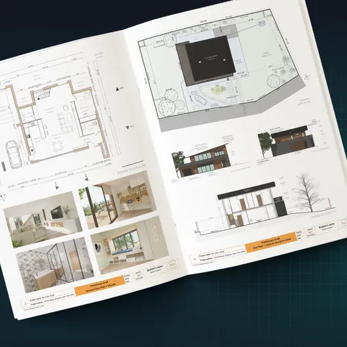
Plans – Get site plans, 2D floor plans, electrical plans, cross sections and elevation views — with all the technical details you need for a comprehensive project overview.
3D Visualizations – Use interior and exterior 3D renderings as well as 3D floor plans to help clients understand the finished project.
Documentation – Manage all your visual documents in one place, so it’s easier to present and sell your projects.
No credit card required, no commitment
What Do Electrical Plans Look Like?
Definition and Purpose of a Home Electrical Layout
In the US, an electrical plan is a scaled drawing of a floor plan that shows the placement of all elements of the electrical systems. This includes electrical components such as lighting, receptacles (electrical outlets), switches, and special-purpose outlets for major appliances like ranges, dryers, and HVAC units.
While it looks like a simple layout, an electrical blueprint is an important tool with several primary objectives:
- Guide for the electrician: It serves as the primary set of instructions for the electrical contractor to follow during the rough-in and trim stages of a project.
- Basis for permitting: A clear electrical plan is required by the local building department, the Authority Having Jurisdiction (AHJ), to obtain a building permit. The plan must show that the design complies with the National Electrical Code (NEC) and any local amendments.
- Accurate bidding and costing: The plan allows you and your electrical subcontractor to accurately estimate the cost of materials and labor.
- Client communication and approval: It acts as a visual confirmation for the client to review and approve to make sure their needs for power and lighting are fully met before construction begins.
- Compliance check: The electrical inspector will use the approved plan as the reference document to verify that the finished work is installed to code.
Electrical Plans vs. Wiring Diagrams: What’s the Difference?
This is a crucial distinction that’s often misunderstood in the industry. Though the terms are sometimes used interchangeably, an electrical plan and a wiring diagram serve two very different functions.
- An electrical plan, which is also called an electrical layout, is a locational drawing. Its purpose is to show where electrical components are physically located on the floor plan. This is the document that guides the physical installation of electrical outlets, switches, and light fixtures. It typically does not show the exact path of the electrical wiring.
- A wiring diagram, on the other hand, is a functional drawing. It is a pictorial representation that shows how the components are physically wired together, including wire routing and connection points.
- Schematic diagrams are similar to wiring diagrams. Electrical schematic diagrams are purely functional drawings that illustrate the logical flow of an electrical circuit. They use basic schematic symbols to represent the circuit’s components and show how the circuit functions electronically without showing the physical layout, size, or shape of the components.
For most residential projects, the primary document used is the electrical plan.
To provide functional detail without cluttering the drawing, a Panel Schedule is used alongside the plan. This table details each circuit in the breaker panel, specifying the circuit breaker size and the rooms or devices it serves.
This coordination between the Panel Schedule and Electrical Plans is essential since NEC Section 408.4(A) requires every circuit and circuit modification to be legibly identified as to its clear, evident, and specific purpose or use. This identification must be located on a circuit directory on the face or inside of the panel door. An accurate, field-verified panel schedule is the source document used to create this permanent directory.
What to Include in Residential Electrical Drawings & How to Draw Them
A professional electrical plan is a universal language spoken on the job site. To ensure everyone, from the electrician to the inspector, knows how to read electrical schematics from your company, every element should be represented clearly and consistently. Here’s a breakdown of the key components.
Proper Representation: Electrical Symbols and Standards
In the US, the symbols used on electrical layouts are influenced by standards from the American National Standards Institute (ANSI), specifically ANSI Y32.9.
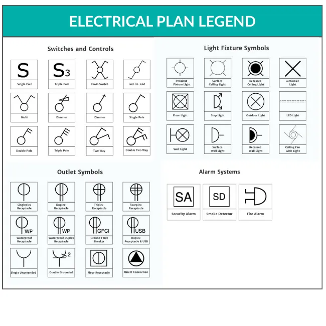
While these standards exist, the single most critical practice is to include a legend or symbol key on all your electrical drawings. This simple table defines every symbol used in the drawing so there’s no room for guesswork or misinterpretation.
Why does this matter?
- It reduces errors: Standardized symbols prevent costly mistakes, like an electrician installing a standard 120V outlet where the plan called for a 240V appliance outlet.
- It improves efficiency: A clear legend allows the builder, electrician, and inspector to understand the plan at a glance.
- It enhances communication: It creates a common language for everyone involved in the project.
The Electrical Panel (Load Center)
The heart of the system is the electrical panel, also known as the load center or breaker box. This is where the main power from the utility enters the home and is distributed into individual circuits, each protected by a circuit breaker.
Because this is the main hub for the entire system, the National Electrical Code (NEC) has very strict rules about its location:
- The panel must be in a readily accessible location. It cannot be in a bathroom or a clothes closet.
- A clear working space must be maintained in front of the panel as required by NEC Section 110.26(A).
How to represent on the plan:
On the plan, the panel is typically represented by a simple rectangle labeled “PANEL” or “LP” (for Lighting Panel).
Receptacle Outlets
What are commonly called “plugs” are officially known as receptacles or outlets. The NEC dictates their placement to ensure both safety and convenience.
How to represent on the plan:
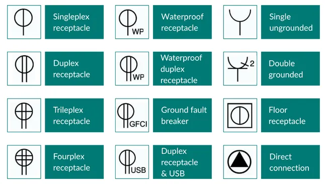
- Standard duplex receptacle: This is the most common outlet found in a home. It is represented by a circle with two short, parallel lines drawn through it. This is the workhorse symbol for general-purpose outlets in living rooms, bedrooms, and hallways.
- GFCI receptacle: To indicate a Ground-Fault Circuit Interrupter outlet, which is required for safety in locations like bathrooms, kitchens, and garages, you use the standard duplex symbol and simply add the letters “GFCI” next to it. This annotation is a clear instruction for the electrician.
- Special-purpose outlets: Major appliances like an electric range, clothes dryer, or HVAC unit require their own dedicated outlets. These have unique symbols, often a circle with different line configurations, and must be clearly labeled for their intended use (e.g., “RANGE,” “DRYER”).
- Other common variations: A quad receptacle (with four outlets) is often shown with four lines instead of two. An exterior outlet will include the letters “WP” (Weatherproof) or “WR” (Weather-Resistant) next to the symbol.
Lighting Switches
Electrical diagrams need to detail both the fixtures and their controls. The NEC generally requires at least one wall-switch-controlled lighting outlet in every habitable room, bathroom, hallway, and attached garage.
How to represent on the plan:
The plan must clearly show which switch controls which light(s). This is typically done with a curved dashed line connecting the switch symbol to the light symbol.
On standard US electrical plans, the symbols for common switches are straightforward:
- Single-pole switch (S): This switch controls a light from one location. Its symbol is a simple capital “S” placed on the wall line of the floor plan.
- Three-way switch (S₃): Used in pairs to control a single light from two different locations (e.g., the top and bottom of a staircase). This is represented by an “S” with a subscript “3”. Follow the same pattern for a four-way switch.
Key Safety Requirements: GFCI & AFCI Protection
Modern electrical codes mandate two critical types of protection that should be clearly identified on your plan: GFCI (Ground-Fault Circuit Interrupter) and AFCI (Arc-Fault Circuit-Interrupter).
How to represent on the plan:
To ensure compliance, the plan must clearly indicate where this protection is required. This is typically done in one of two ways:
- Symbol annotation: Place a note next to the standard receptacle symbol. For example, a duplex receptacle requiring ground-fault protection would be marked with ‘GFCI’.
- Circuit-level notation: If the entire circuit is protected by a GFCI or AFCI circuit breaker in the panel, a note can be added to the homerun arrow (e.g., ‘CKT #5, 20A AFCI’) and in the panel schedule. This is the common method for AFCI protection.
Special Equipment and Dedicated Circuits
Your plan must also account for major appliances that require their own dedicated circuit. A dedicated circuit has its own circuit breaker in the panel and serves only one appliance to ensure it has enough power without overloading the system.
How to represent on the plan:
The plan should use a specific symbol for these connections, often a special-purpose outlet, clearly labeled for its function (e.g., “RANGE”).
Circuits and Homeruns
Instead of drawing messy lines for every wire, US electrical plans use a clean system to show how devices are circuited. This is done with homeruns.
How to represent on the plan:
A homerun is a short arrow that points from a group of devices toward the electrical panel. This arrow is labeled with a circuit number (e.g., “3,” “5,” “7”) that corresponds to the circuit’s slot in the panel schedule. All the outlets, lights, and switches connected by dashed lines before that homerun arrow are on that same circuit.
How to Create a Coherent and Legible Electrical Floor Plan
A good electrical plan is more than just a collection of symbols on a page. It’s a clear and actionable roadmap. The process for creating one should be just as logical and methodical. By following a structured approach, you can ensure that you cover all the bases, from client needs to code compliance.
The Steps to Building a Professional Electrical Plan
Building a professional electrical layout involves a few key stages.
Step 1: The Client Lifestyle Interview
This is the most important step. Before you draw a single line, you need a deep understanding of how the client will live in the home. Go beyond the basics.
- Instead of asking, “Do you work from home?” ask, “Where will you work? What specific equipment do you use? Will you need a hardwired internet connection there for stable video calls?”
- Think about furniture placement. Ask for a basic furniture layout to avoid placing critical outlets behind a king-size bed or a large bookcase.
- Ask about the future. “Do you think you might ever own an electric vehicle? Are you planning for a workshop in the garage or a hot tub out back down the line?”
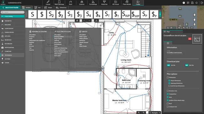
Step 2: Choose a Suitable Drawing Tool
In today’s market, drawing electrical plans by hand is inefficient and looks unprofessional. Tools like Cedreo allow you to create clean, scaled, and easily editable electrical layouts as part of your overall design process. This saves an incredible amount of time and hassle.
Step 3: Place Devices and Equipment
Starting with a clean, scaled floor plan, begin placing the symbols for outlets, switches, and lights. Think logically about workflow and convenience.
- In the kitchen, where will the coffee maker, stand mixer, and air fryer likely live? Place outlets on the countertop accordingly.
- In bedrooms, always place a switch at the entry door. Position outlets on both sides of where the bed will go for lamps and chargers. A switch by the bed that controls an overhead light is a high-value touch.
- In living rooms, consider where the TV and media components will be and place a cluster of outlets and low-voltage connections there. Add outlets near couches and chairs for lamps and device charging.
Step 4: Verify NEC and Local Code Compliance
This is a non-negotiable step. Go through your plan room by room and check it against the current National Electrical Code requirements.
- Is the wall receptacle spacing correct?
- Are all the required GFCI and AFCI protected outlets properly marked?
Always remember to consult your local building department, as they often have amendments that are more stringent than the base NEC.
Step 5: Refine, Annotate, and Share
A clean plan is a useful plan. Before sharing it, clean up the layout for maximum legibility.
- Add a detailed legend: Ensure every single symbol on the plan is defined in your legend.
- Use annotations: Add text notes for anything that isn’t obvious. E.g. Specify the mounting height for a wall-mounted TV outlet or for wall sconces.
- Check scale and symbol size: Make sure the symbols and text are large enough to be easily read when printed on standard architectural sheet sizes, like 24″ x 36″.
4 Common Mistakes to Avoid in Your Electrical Blueprints
Even with the best intentions, it’s easy to make mistakes on an electrical plan that can cause confusion on site. Here are four of the most common pitfalls and how to steer clear of them.
1. Using Unconventional or Undefined Symbols
Using a symbol that isn’t standard, or worse, not including it in your legend, is a recipe for disaster. It forces the electrician to guess what you meant, which can lead to incorrect installations, failed inspections, and costly rework. The plan is not the place to get creative with your symbols.
2. Visually Overloading the Plan
A cluttered plan is a useless plan. Trying to cram too much information into a small space makes the entire drawing difficult to read and increases the chance of errors. This often happens in dense areas like kitchens or home theaters.
The solution is to create separate, enlarged floor plan details for these complex areas. This allows you to clearly place all the necessary symbols without them overlapping.
Also, avoid the temptation to draw the exact path for every wire. That’s not the job of an electrical blueprint. Use clean homerun symbols to indicate the circuit, and let the electrician determine the most efficient wire routing on-site.
3. Forgetting Legends and Annotations
Assuming a plan is self-explanatory is a major pitfall. Always include a comprehensive legend and add clarifying text notes for anything out of the ordinary. Be specific. It’s the details that turn a good plan into a great one.
4. Inconsistency Across Documents
Using one set of symbols for one project and a different set for the next creates confusion for your trade partners. True professionals develop a consistent “brand standard” for their plans.
When your electricians and inspectors see your name on a set of electrical blueprints, they should know they are getting a clear, consistent, and reliable document every time. This builds trust, speeds up their workflow, and dramatically reduces the number of questions and callbacks you have to field.
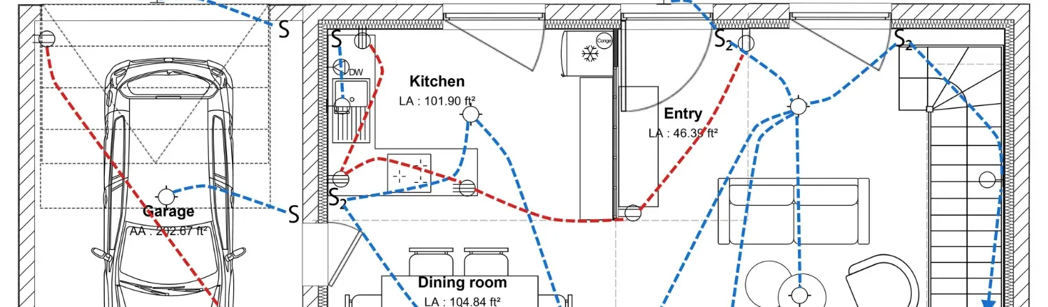
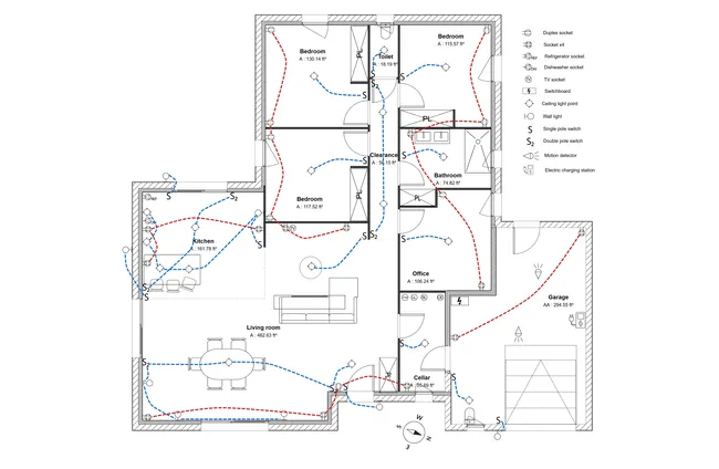
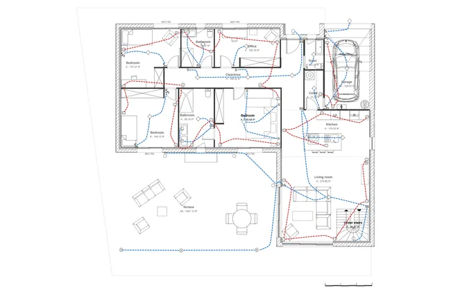
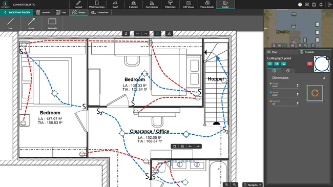
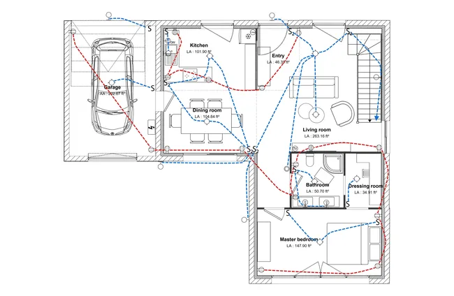
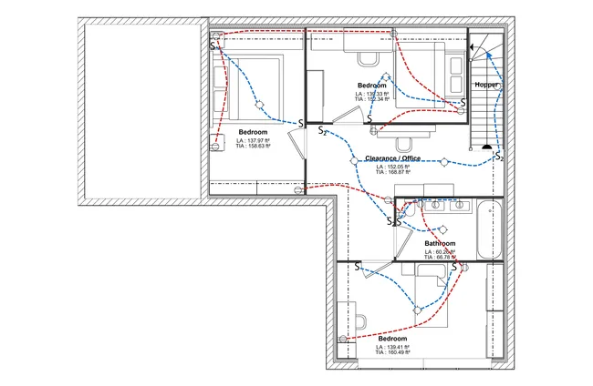
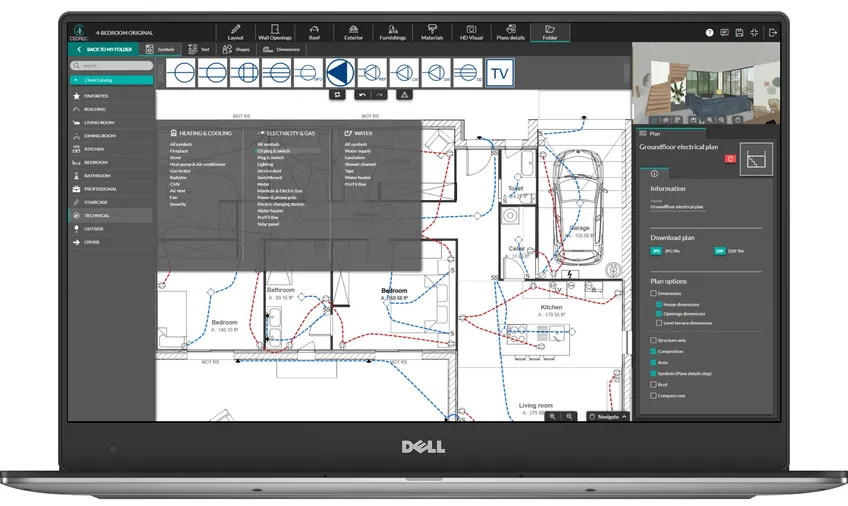
Electrical Plan Examples
Now that you understand the theory and the steps involved, it’s helpful to see what a finished electrical plan looks like. A well-drafted plan is clean, legible, and easy to interpret at a glance.
Below are a few electrical plan examples created with Cedreo’s modern design software. Notice how they use a clear legend, consistent electrical symbols, and annotations to provide a complete picture for the client and the electrician.
Future-Proofing the Electrical Installation: Best Practices
The homes you build today will be in use for decades, but technology and lifestyles change fast. A truly professional electrical plan doesn’t just meet today’s code, it anticipates tomorrow’s needs. This forethought adds immense value for your clients and prevents costly future renovations.
Here are a few best practices for future-proofing your electrical installations:
- Reserve space in the panel: Always install a panel with at least 20-25% more breaker spaces than you currently need. Adding a circuit to a full panel is an expensive, time-consuming job that may require a sub-panel or a full panel replacement. In contrast, adding a new breaker to an empty slot is simple and cheap.
- Go beyond code minimums for outlets: The NEC dictates the minimum number of outlets required for safety. In a world full of smart devices, TVs, and electronics, the minimum is rarely enough for convenience. Adding extra receptacles in home offices, bedrooms, and media centers prevents the unsafe use of power strips and extension cords.
- Electric vehicles (EVs): Run a conduit from the electrical panel to the garage. This makes the future installation of a Level 2 EV charger incredibly simple and is a huge selling point for homeowners.
- Low-voltage wiring: While Wi-Fi is great, it’s not always stable enough for home offices or streaming 4K video. Run structured wiring (like Cat6 Ethernet and RG6 Coax) to key locations to provide reliable, hardwired internet connections.
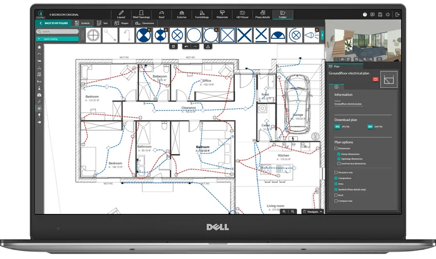
Cedreo: The Ideal Solution for Your Electrical Plans
Cedreo is engineered for home builders, remodelers, and designers who need to create professional electrical plans without the steep learning curve of traditional CAD. Cedreo is a 100% online home design software that empowers you to create your electrical plans directly on your 2D floor plan.
With Cedreo, you can streamline your entire design process:
- Work faster with an intuitive drag-and-drop interface.
- Use a complete library of standardized electrical symbols for outlets, switches, lights, and more.
- Add clarity with custom annotations, dimensions, and a detailed legend.
- Instantly visualize layouts in 3D, helping you and your client spot potential issues before construction.
- Export professional documents ready for client presentations and your electrical contractor.
In just a few clicks, you can produce a legible, professional electrical blueprint that is immediately usable on the job site.
Create your next house electrical plan drawings with Cedreo.
Electrical Plan FAQ
An electrical plan is a visual representation showing the location of fixtures, switches, and outlets on a floor plan. A wiring diagram is a more technical electrical diagram that shows how all the components of an electrical circuit are functionally connected, without regard to their physical location.
In the US, every electrical blueprint must comply with national and local safety standards, primarily the National Electrical Code (NEC). Following these codes is essential for ensuring safety, preventing potential hazards, and creating reliable electrical systems. Your local building authority may have additional requirements.
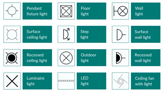
The key elements of a plan include the main power sources (like the electrical panel), locations for various appliances, and where to place switches and other fixtures. The plan can also detail places for different lighting types, such as ambient lighting, accent lighting, and task lighting, and include a legend explaining all the symbols used.
Electrical symbols need to provide a clear visual language on electrical drawings. Each symbol represents specific components or fixtures, while lines are used to represent the wires that connect them into circuits. The most important rule is to always include a legend so everyone on the job site understands what each symbol means.
Absolutely. Cedreo is an ideal tool for builders and interior designers to create a complete electrical blueprint. You can easily drag and drop all the necessary components onto your floor plan from a built-in library of standardized schematic symbols to create a professional electrical plan in minutes.
To read electrical drawings, start by reviewing the legend to understand what each symbol represents. Locate the main electrical panel, then trace the lines (which show the path of the wires) to see how components are grouped into circuits. Special notes will indicate unusual components or specific locations of fixtures to help you understand the complete electrical system.