Electrical layouts, wiring diagrams, and installation plans…every one of these technical documents relies on clear and consistent visual representations of electrical symbols. And for a project to run smoothly, everyone on your team needs to speak the same visual language used in those documents.
That’s where having a set of standardized electric symbols comes in.
What are the most common symbols used in floor plans? Why does consistency matter so much? And how can you avoid miscommunications and ensure all the electrical components get installed correctly?
In this guide, we’ll walk you through the basics of how to accurately and professionally represent your electrical layout.
Key Takeaways
- You need standardized electrical symbols: Your plans must be clear, readable, and compliant with industry norms, so that any electrician or inspector can understand them quickly.
- Standardization boosts safety and efficiency: Using universally recognized symbols reduces the risk of interpretation errors, speeds up plan reading, and streamlines communication across teams.
- Each symbol has a specific meaning. For example, standard duplex outlets are shown as circles with two parallel lines drawn through them, switches are represented by the letter S, common light fixtures as circles, and electrical panels as rectangles.
- Cedreo simplifies electrical plan creation. With Cedreo’s built-in library of standardized electrical symbols (that you can customize by size, shape, and color), you can create detailed, professional layouts that align with your brand and meet each project’s requirements.
Why trust us? Here at Cedreo, we’ve got 20+ years of experience working with housing pros in the home design space. We know what it takes for home builders, contractors, and designers to create accurate electrical plans faster than ever!
See How You Can Create Complete Projects with Cedreo
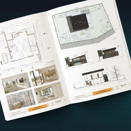
Plans – Get site plans, 2D floor plans, electrical plans, cross sections and elevation views — with all the technical details you need for a comprehensive project overview.
3D Visualizations – Use interior and exterior 3D renderings as well as 3D floor plans to help clients understand the finished project.
Documentation – Manage all your visual documents in one place, so it’s easier to present and sell your projects.
No credit card required, no commitment
Electrical Blueprint Symbols: What Regulations Apply to Your Floor Plans?
In the U.S., electrical symbols used in residential plans are guided primarily by the National Electrical Code (NEC). While the NEC doesn’t dictate specific graphical icons for every electrical element, it does require that your diagrams be:
- Clearly legible and easy for professionals to interpret
- Consistent in how symbols represent fixtures, wiring, and systems
- Aligned with standard practices recognized across the industry
While U.S. residential plans primarily follow conventions from the American National Standards Institute (ANSI) and the Institute of Electrical and Electronics Engineers (IEEE), it can be helpful to be aware of the IEC 60617 standard for international projects. This global system includes over 1,400 symbols for everything from outlets to automation systems.
Using these standardized symbols in your architectural plans and electrical blueprints ensures clarity, improves safety, and helps your project comply with building code documentation expectations.
Note: “Electrical Symbols” can include symbols for electrical circuits, electronic symbols, and communication symbols. In this article, we’re focusing on the most common symbols used in residential construction documents in the United States.
Why It’s Important to Have a Standardized Set of Electric Symbols
Standardizing your electrical symbols isn’t just about code compliance. It’s a best practice that adds real value to your construction documentation. Here’s why:
- Greater safety: Clear, consistent symbols reduce the risk of misinterpretation during installation. This prevents expensive mistakes and avoidable hazards on the job site.
- Time savings: A standardized plan can be read and understood at a glance. There’s no need to decode custom icons or figure out what each fixture represents. This speeds up work on-site and simplifies inspections.
- Better team coordination: Multiple contractors and trades often touch the same project. When everyone uses the same visual language, handoffs are smoother and there’s no confusion when reviewing plans.
So using proper electrical symbols shows your professionalism, builds trust, and enhances communication across your entire project team.
Electrical Symbols on Floor Plans Every Builder Should Know
Knowing which electrical symbol to use and when is essential for creating clean, easy-to-read electrical plans. Here are the main categories and examples of symbols that you’ll use in residential floor plans.
Important! There are subtle variations to these symbols used on residential plans in North America. That’s why it’s important to choose a standard set of symbols. If you use Cedreo design software, you don’t have to worry about that since it’s got a library of special symbols for electrical, HVAC, plumbing, and more.
Electrical Outlet Symbols
Electrical wall outlet symbols appear on nearly every plan. And each outlet type has its own standard symbol for quick identification. Here are a few common examples:
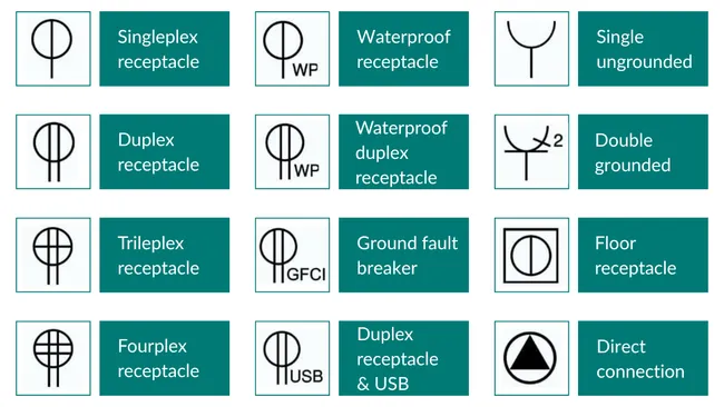
- Standard outlet: The common 120V duplex receptacle with two sockets is represented by a circle with two short, parallel lines drawn through it. If there is just one line coming from the circle, then it’s an outlet with a single receptacle.
- Dedicated appliance outlet (dishwasher, oven, clothes dryer, refrigerator, etc.): Often a standard outlet symbol or a triangle within a circle. They’ll be labelled with something like “DW” (dishwasher), “REF” (refrigerator) or “CD” (clothes dryer) and sometimes include the amperage.
- USB outlet: Typically shown as a standard outlet with an added “USB” label or a variation of the circle symbol with a tag.
- Other notes: To clarify what type of outlet it is, add notes, such as “GFCI”, to standard outlet symbols.
PRO TIP! If an outlet is installed at a non-standard height…for example, above a countertop or near the floor, always indicate the mounting height directly on the plan. This eliminates guesswork for the electrician during installation.pas à indiquer sur votre plan électrique la hauteur d’implantation à respecter.
Electrical Switch Symbols and Lighting Controls
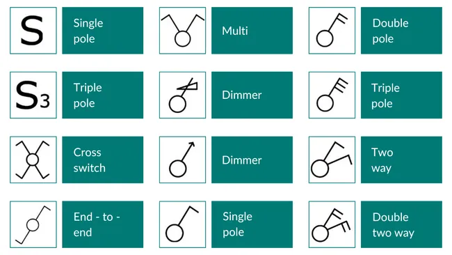
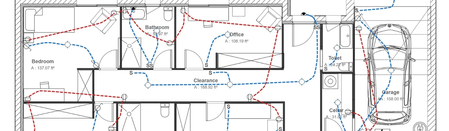
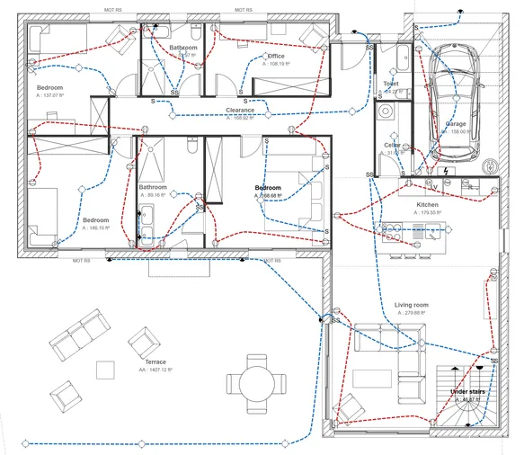
Switches are used to control lighting circuits and should be placed for easy access, typically near doorways or room entries. On electrical plans, it’s common to show how each switch connects to the fixtures it controls using curved lines.
Depending on the type of control and the number of fixtures involved, here are a few common switch symbols:
- Single-pole switch: The letter S, sometimes with a line through it $.
- Double-pole switch: The letter S with a subscript 2 (S₂).
- 3-way switch (used for controlling lights from two locations): The letter S with a subscript 3 (S₃).
- Dimmer switch: The letter S with a subscript D or DM (Sᴅ), indicating adjustable brightness. Sometimes also a box with a D in it is used.
Light Fixture Symbols and Circuits
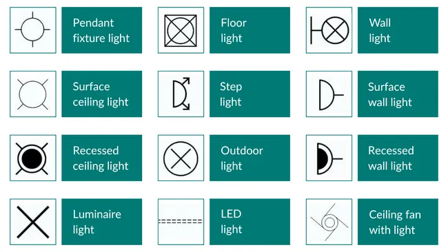
Lighting placement is critical for ensuring comfortable visibility throughout the home. Each fixture type has its own visual representation. Common examples include:
- Ceiling light (surface mounted): A simple circle or rectangle. There are many variations to this, so it’s important to establish a standard for your projects and clearly label it in the plan’s symbol legend.
- Wall mounted fixture: A full circle attached to the wall, with a small line extending from the circle to indicate the fixture’s position. Sconces are sometimes represented by half circles.
- Recessed light: Typically shown as a plain circle. To avoid confusion with standard ceiling lights, it is often labeled with “R” or “REC” or defined in the plan’s symbol legend.
- Spot light: A circle with one or more triangles, depending on how many heads the spotlight has.
PRO TIP! For exterior or wet-location fixtures, use a modified symbol, such as a hatch pattern or an “WP” (weatherproof) tag, to indicate moisture protection. This is especially important for compliance with outdoor and bathroom electrical codes.er cette caractéristique.
Electrical Panel Symbols
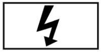
Your electrical panel is the heart of your home’s power distribution, and its location and symbol must be clearly marked on every electrical plan. Since all circuits originate from this central hub, placing the panel strategically helps minimize wiring distances for efficient installation.
On U.S. floor plans, the electrical panel is typically represented by a rectangle with a lightning bolt icon or labeled with “Main Panel”.
Special Electrical Equipment to Include
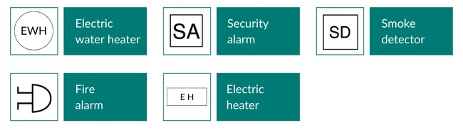
Beyond the basics (outlets, switches, and lighting), there are other electrical devices and appliances you need to represent on your plans.
Here are key items to include:
- Electric water heater: Typically shown as a circle labeled “WH” (Water Heater) or “EWH” (Electric Water Heater).
- Smart home systems, alarms, and connected tech: Use generic device icons with clear text labels (e.g., “Smart Hub,” “Security Alarm”).
- Miscellaneous power feeds: For devices like motorized blinds or outdoor equipment, use the symbol for a special-purpose outlet (such as a single receptacle symbol labeled appropriately or a standard receptacle with a triangle) and add a clear text annotation (e.g., “Motorized Blinds”).
- Electric heaters: Usually drawn as a rectangular box or bar with a label showing wattage (e.g., “1500W Baseboard Heater”).
PRO TIP! Always include custom annotations when using symbols for specialty devices. It keeps your plan clear and saves time during installation. Fortunately Cedreo makes it easy to add custom shapes and annotations.
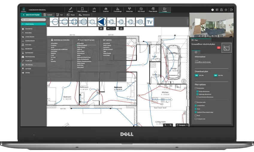
Create a Floor Plan With Electrical Symbols Faster with Cedreo
Draw electrical symbols on floor plans the easy way with Cedreo home design software. Here’s how.
A Complete Library of Electronic Symbols
Cedreo gives you access to a comprehensive, regularly updated library of electrical wiring diagram symbols and electrical abbreviations, so you’re always following current best practices and keeping all your plans consistent.
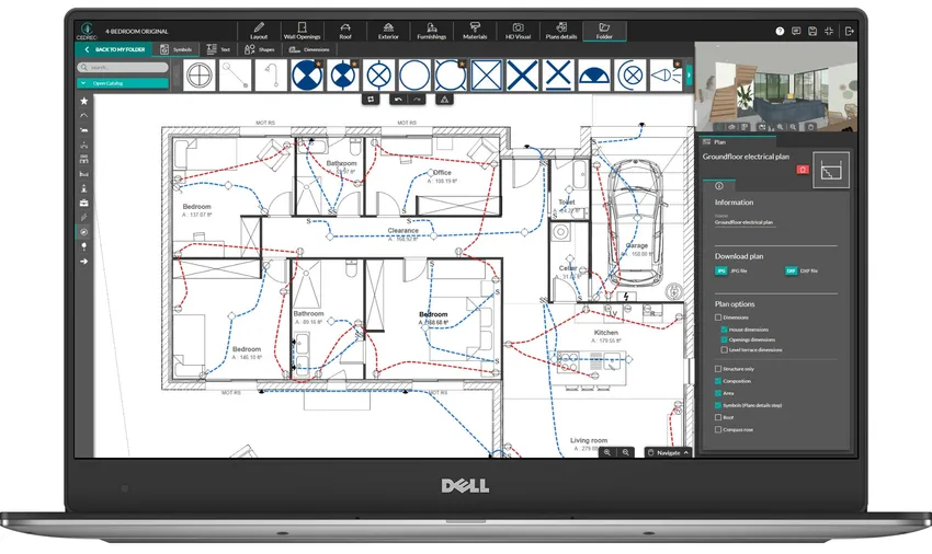
From standard and dedicated outlets to switches, lighting points, panels, smart home devices, and more, Cedreo includes everything you need to create clean, code-friendly electrical layouts.
With just a few clicks, you can build professional-quality electrical diagrams that are easy for clients and contractors to interpret on-site, no additional CAD tools required.
Advanced Customization for Every Project
All symbols in Cedreo are pre-configured for ease of use, but they’re also fully customizable to match your unique workflow or project needs.
- Add custom notes to provide additional information
- Adjust size, shape, color, and scale
- Align plans with your internal design standards or visual branding
- Use color coding to visually separate circuits for improved readability
- Draw curved lines from switches to recessed lights and other fixtures to show how they’re connected
PRO TIP! Save your most-used symbols as favorites, so you can drag and drop them into any plan without hunting through the symbol library.
Cedreo turns your electrical diagrams into powerful communication tools. Every feature is designed to improve clarity, save time, and help you present polished, professional plans every time.